|
TPC tries to coordinate paper size and margins so that layouts plot the same from both CAD and TPC.
This is somewhat dependent on your CAD program being able to use the same Windows printer names and form names (paper sizes) that TP uses.
Exporting to CAD
When exporting a DWG drawing, TPC embeds the printer and paper form names into the layout. When opened in CAD, the CAD page setup for the layout should reference those properly.
To avoid issues with paper margins, TPC sets the origin of an exported layout to the lower-left user margin selected for the TPC drawing.
Extra Border Margins
The Border Properties dialog includes a Margins section that allows you to increase the border margins while still allowing you to draw withing the Windows printer margins specified in the Page Setup dialog.
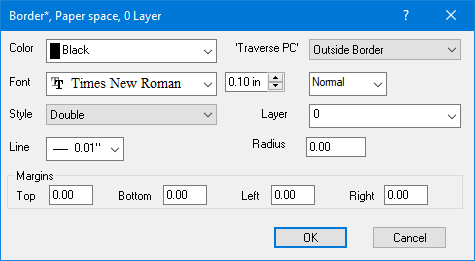
The additional Margins you set here does not affect the CAD layout TPC exports for the drawing. That layout is still dependent only on the drawings Page Setup size, orientation and margins. As such, TPC draws the border on the CAD layout exactly where it draws it in the TPC drawing.
Importing from CAD
When importing a DWG layout, TPC reads the embedded printer name, form name (paper size), orientation and margins in the layout.
If these differ from those in the drawing you are importing into, TPC prompts you to adjust the TPC drawing to match.
•Responding with Yes, allows TPC recreate the layout as accurately as possible.
•Responding with No allows you to import the layout into your drawing without changing its size or orientation.

Related Topics
Using Layouts
Page Setup dialog
Editions
Premium, Professional
|

