|
The Polyline command inserts multiple line segments into the drawing using the current line type, line width and color of the Drawing View Format Bar. Unlike the Line command, the line segments are part of a single object, the Polyline, and can be edited and moved together.
Polylines are appropriate for any boundary or feature where you want all the line segments to be the same. In addition, Polylines can be filled with a color.
•Select the mode you want to draw the text in - Paper Space or Survey Space.
•From the Format toolbar, choose the line type, width and color. You can change the properties of the line at any time, but you will save time by selecting them first.
•Choose Draw | Polyline. The cursor will change to a tick (cross) indicating that Drawing View is looking for an insertion point.
•Move the cursor to the insertion point and left click. Notice that the status bar displays the location of the tick mark in both survey and paper coordinates. You can also snap on another object to pick the insertion point.
Drawing View draws a line from the first insertion point to the cursor as you move it. This indicates the next segment to be added by the command. When you left click, a segment will be added and the mouse will advance to the next line segment. Create as many segments as you need.
•To enter an exact bearing and distance, hold down the left Shift key and left click near the desired endpoint. TPC displays the line dialog box. You can enter the bearing, distance, end point coordinates, etc. Choose OK when finished and TPC will redraw the line to the desired specifications.
•To draw a line North-South or East-West, first move the cursor in the desired direction, then hold down the Ctrl key to put Drawing View in Ortho mode and drag the mouse to the desired position.
•Right click or press [Enter] again to finish the command.
To cancel the text command anytime before you finish, press the [Esc] key.
Smooth Polylines
To smooth a polyline,
•Right click the polyline and choose Properties.
•Choose Curve Fitting and specify a Max Offset and Tension.
•Choose OK.
See Polyline Smoothing.
Drawing Traverses as Polylines
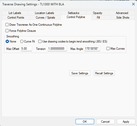
Beginning in TPC Desktop 2020, any traverse can be drawn as a polyline. The Traverse Drawing Settings include a new tab called Control Polyline. Just tell TPC you want to draw a traverse as a polyline and specify any smoothing you want to apply to it.
Some projects require that features like parcel boundaries, road centerlines, etc. be drawn with continuous, 3D polylines. This option draws the control points of the traverse as a single polyline which can then be exported directly to any CAD file.
This tools is also handy way to easily smooth features like wetland and vegetation boundaries.
Convert to Survey
When you convert a polyline to a traverse, TPC looks at these settings to determine how to create the new traverse for the polyline.
If the polyline closes back on itself (the last vertex has the same coordinates as the first vertex), the created traverse's closure type will be set to Closed Loop.
If the polyline does not close back on itself, it is drawn as closed or not depending on the polyline's [x] Closed setting. TPC duplicates this for the created traverse if the traverse's Traverse Drawing Settings use this option to draw the traverse control lines as a continuous polyline. In this case, TPC sets the [ ] Force Polyline Closure option mentioned above to match the [ ] Closed setting of the polyline.
If you smooth a polyline, then convert it to survey, TPC creates a traverse with the smoothed geometry and area.
Related Topics
Drawing Commands
Editing Drawing Objects
Filling Drawing Objects
Using Drawing View
Smart Drawing Objects
Working with Drawing Objects
Drawing Commands
Editions
Personal, Premium, Professional
|

