|
TPC can draw control lines for any traverse as a single, continuous, polyline. Instead of individual line segments for each traverse course, TPC draws just one single polyline, formatted to match the traverse's tangents, arcs and spirals.
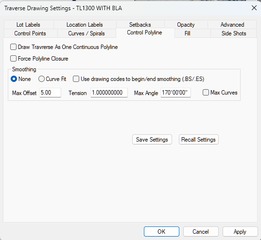
To turn on control polylines, turn on the [X] Draw Traverse as One Continuous Polyline option in the Control Polyline Dialog.
3D Polyline
TPC draws the traverse control lines as one, continuous, 3D polyline. This means that each vertex will have the elevation of the survey point it represents.
Required Output
The project you are working on may sometimes require that features like parcel boundaries, road centerlines, stream centerlines and so on, be exported to CAD as polylines. This option does just that. If you turn it on, the polyline that TPC draws for the traverse is carried all the way through to CAD exports.
Polyline Settings
TPC uses the Control Point settings to draw the polyline. These include line type, line width, line color, layer, etc.
The polyline segments are also labeled just like the line segments would be labeled, using the Control Point settings.
Fills
If you draw a traverse as a polyline, the Fill Traverse Drawing Settings will still fill the polyline and place that fill on a separate TpcFills layer so you can turn all fills On or Off by turning that layer On or Off.
However, the polyline generated to draw the traverse can also be filled by itself, by changing the fill in it's Properties dialog. This fill will be drawn as the same layer as the polyline.
Symbol Clearing
When you draw control points as individual line segments, you have two options to trim the lines out of the point symbols used for that traverse
•turn on the [x] Trim Symbols option in the Control Point settings
•use the Clear Background options in the Drawing Settings
When you draw a traverse as a polyline, the polyline is continuous, so [x] Trim Symbols can not be used.
The Clear Background option does work, but requires that the layer the symbols are one be in front of the layer the traverse polyline is on. See Drawing Order.
Force Polyline Closure
If the traverse does not close, you can force it to draw closed by turning on the [x] Force Polyline Closure option. This same option is available to any polyline as [x] Close in the Polyline Properties dialog.
Polyline Smoothing
One of the advantages of drawing a traverse as a polyline is applying smoothing to the polyline. This can add a nice touch to certain boundaries like wetlands and vegetation that you want to represent in your drawings.
TPC uses the same smoothing routine it uses for controur smoothing, ensuring that the smoothed lines pass through the polyline vertecies, making the smoothed polyline as accurate as possible by including the measured points.
See Traverse Smoothing.
Convert to Survey
When you convert a polyline to a traverse, TPC looks at these settings to determine how to create the new traverse for the polyline.
If the polyline closes back on itself (the last vertex has the same coordintes as the first vertex), the created traverse's closure type will be set to Closed Loop.
If the polyline does not close back on itself, it is drawn as closed or not depending on the polyline's [x] Closed setting. TPC duplicates this for the created traverse if the traverse's Traverse Drawing Settings use this option to draw the traverse control lines as a continuous polyliine. In this case, TPC sets the [ ] Force Polyline Closure option mentioned above to match the [ ] Closed setting of the polyline.
Related Topics
Drawing Control Points
Inserting a Polyline
Control Polyline Dialog
Editions
Premium, Professional
|

